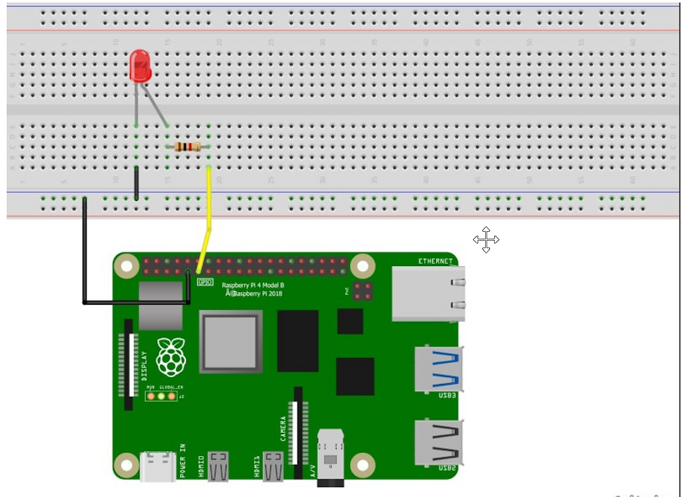
Hardware setup – Make a circuit with your Raspberry Pi and the LED
First of all, make sure your Raspberry Pi is powered off. This is very important. Never plug/unplug any hardware component while your Pi is powered on. You could damage it – for example with an ESD (Electro Static Discharge) – or even completely destroy the CPU if you make a wrong pin connection.
But, don’t worry too much either: if you’re always extra careful and double check everything you do, nothing wrong will happen!
To build this circuit you will need:
A breadboard
A Raspberry Pi with GPIO header
1 LED – the color doesn’t matter
1 resistor: any value between 330 Ohm to 1 k Ohm will be fine. For this example I use 1 k Ohm. To know which color corresponds to which value, check out this website.
A set of male to female wires.
Here’s the schematics to plug an LED to your Raspberry Pi:

Now here are the steps to build the circuit:
Connect one wire between one GND (ground) pin of the Raspberry Pi and the blue line of the breadboard.
Take the LED and check the 2 legs. You will see that one is shorter than the other. Plug the shorter leg to the blue line (now connected to GND), and the longer to any other connector. You can either directly connect the shorter leg to the blue line, or add an additional short male-to-male connector (like in the picture), the result is the same.
Plug one leg of the resistor to the same line as the longer leg of the LED, and the other leg of the resistor to a different line.
Finally, to close the circuit plug one wire between the same line as the other leg of the resistor, and the GPIO number 17 (more on Raspberry Pi pins and GPIOs). This is the 6th pin on the GPIO header, starting from the left, on the inside side.
Writing the Python Software to blink the LED
With the circuit created we need to write the Python script to blink the LED. Before we start writing the software we first need to install the Raspberry Pi GPIO Python module. This is a library that allows us to access the GPIO port directly from Python.
To install the Python library open a terminal and execute the following
$ sudo apt-get install python-rpi.gpio python3-rpi.gpioWith the library installed now open your favorite Python IDE (I recommend Thonny Python IDE more information about using it here).
Our script needs to do the following:
Initialize the GPIO ports
Turn the LED on and off in 1 second intervals
To initialize the GPIO ports on the Raspberry Pi we need to first import the Python library, the initialize the library and setup pin 8 as an output pin.
import RPi.GPIO as GPIO # Import Raspberry Pi GPIO library
from time import sleep # Import the sleep function from the time module
GPIO.setwarnings(False) # Ignore warning for now
GPIO.setmode(GPIO.BOARD) # Use physical pin numbering
GPIO.setup(8, GPIO.OUT, initial=GPIO.LOW) # Set pin 8 to be an output pin and set initial value to low (off)
Next we need to turn the LED on and off in 1 second intervals by setting the output pin to either high (on) or low (off). We do this inside a infinite loop so our program keep executing until we manually stop it.
while True: # Run forever
GPIO.output(8, GPIO.HIGH) # Turn on
sleep(1) # Sleep for 1 second
GPIO.output(8, GPIO.LOW) # Turn off
sleep(1) # Sleep for 1 second
Combining the initialization and the blink code should give you the following full Python program:
import RPi.GPIO as GPIO # Import Raspberry Pi GPIO library
from time import sleep # Import the sleep function from the time module
GPIO.setwarnings(False) # Ignore warning for now
GPIO.setmode(GPIO.BOARD) # Use physical pin numbering
GPIO.setup(8, GPIO.OUT, initial=GPIO.LOW) # Set pin 8 to be an output pin and set initial value to low (off)
while True: # Run forever
GPIO.output(8, GPIO.HIGH) # Turn on
sleep(1) # Sleep for 1 second
GPIO.output(8, GPIO.LOW) # Turn off
sleep(1) # Sleep for 1 second
With our program finished, save it as blinking_led.py and run it either inside your IDE or in the console with:
$ python blinking_led.pyWith the program running you should see something like this:

Thanks for reading !!!